Tribology

Time to bust out the old sonicator – a 1960s Narda SonBlaster 600 that my dad trashpicked about 35 years ago. It’s still going 60W strong. One of the cooler features is a limited tuning function that allows you to max the coupling constant for a given group of parts. It has two tanks and will drive one at a time.

IMG_1437.JPG

The carb parts cleaned up very nicely in a 40/60 mix of Simple Green and water.

IMG_1438.JPG

Although I ordered up some new jets for it, I likely won’t use them. The OE ones are in good shape, and I’d rather re-jet for a slightly richer mix.

The culprit was the air filter – it had a bad day. As far as I can tell, the mess is limited to the intake horn and the carb. I’ll get out the boroscope to check the intake valves tonight. And try to find a new air filter. A paper one would be better, I hate foam filters for exactly this reason.

IMG_1440-1.JPG

My Sherpa decided to no longer fire. I was getting air and spark, but possibly no fuel. Petcock (what magic is this vacuum thing?) is ok.

This little Mikuni is not an SU. Or a Holley. Or a Weber, or a Stromberg, or any other carb I am familiar with.

sherpa_carb0

Slide diaphragm is ok…

sherpa_carb1

Hmmm, was that my air filter?

sherpa_carb2

More to come.

The 11mm Brembo master cylinder fitted to the rear braking system on many Aprilia, BMW, and KTM motorcycles is a weak point, to put it mildly. Regardless, it is fixable. See below for how and why.
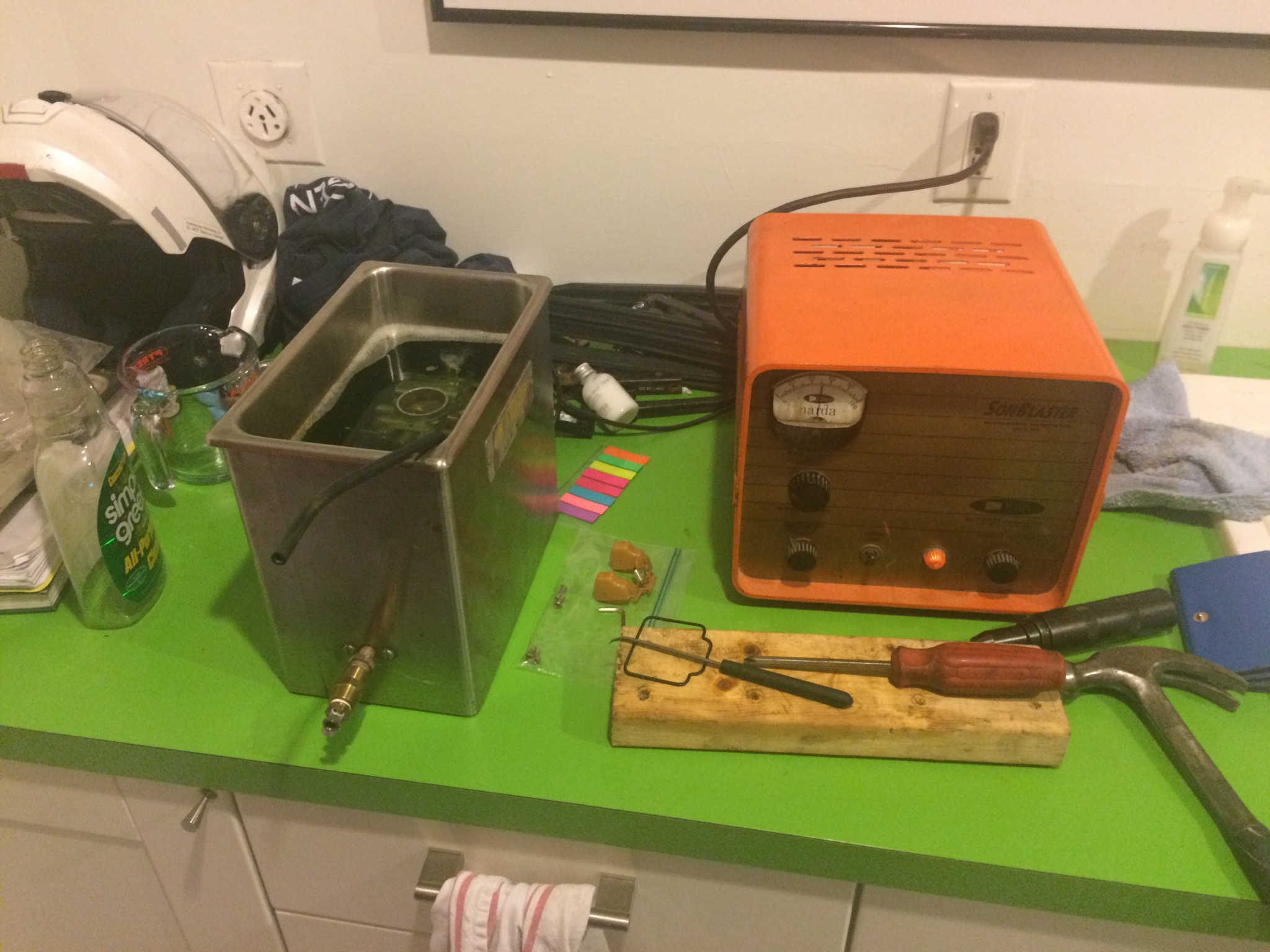
0. Tools required
Inside circlip pliers
10mm socket
5mm hex drive
2mm long drift (10cm) or 2mm Allen wrench
Tack hammer
Long-nose pliers
Flat-head screwdriver
Dental picks
Dremel with small round cutting bit
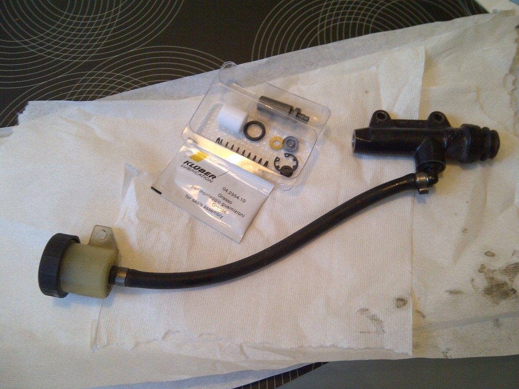
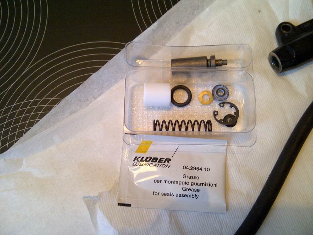
One full rebuild kit from Brembo, part number 110.4362.41

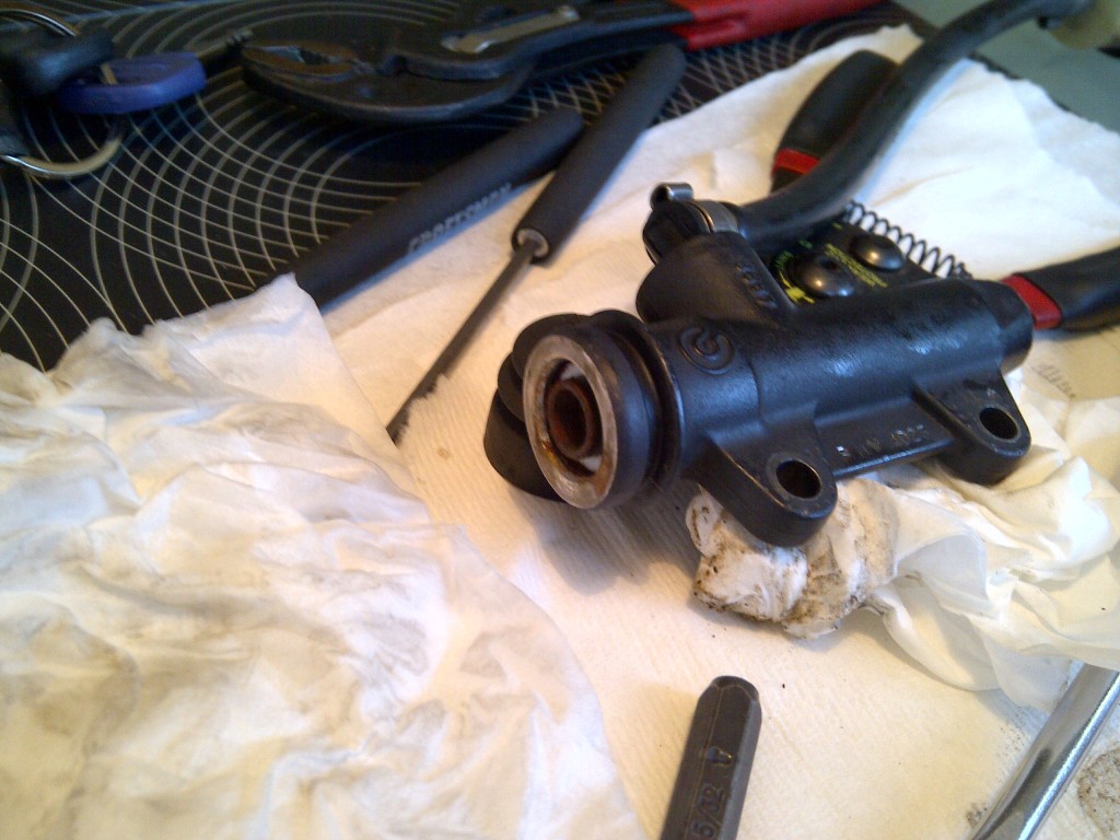
1. Remove the master cylinder from the bike. To do this, remove the bolt holding the brake fluid reservoir and washer with a 10mm socket. Return the bolt and washer to the hole to insure they are not lost. Drain the reservoir and replace the lid and gasket. Release the brake line fitting from the top of the master cylinder and back it out entirely. Remove the two bolts securing the MC to the bike using a 5mm hex drive. Lift the MC away from the bike, clearing the brake line at the top. The push rod will slide out of the rubber boot at the bottom with a slight tug. Return the two hex screws to the bike for safekeeping.

2. Retire to somewhere warm (or cool…), you might be there for a while. Bring the MC with you. Spread some paper towels or other protection out, and drain the master cylinder fully. Set aside the rebuild kit for later.

IMG-20130113-00182

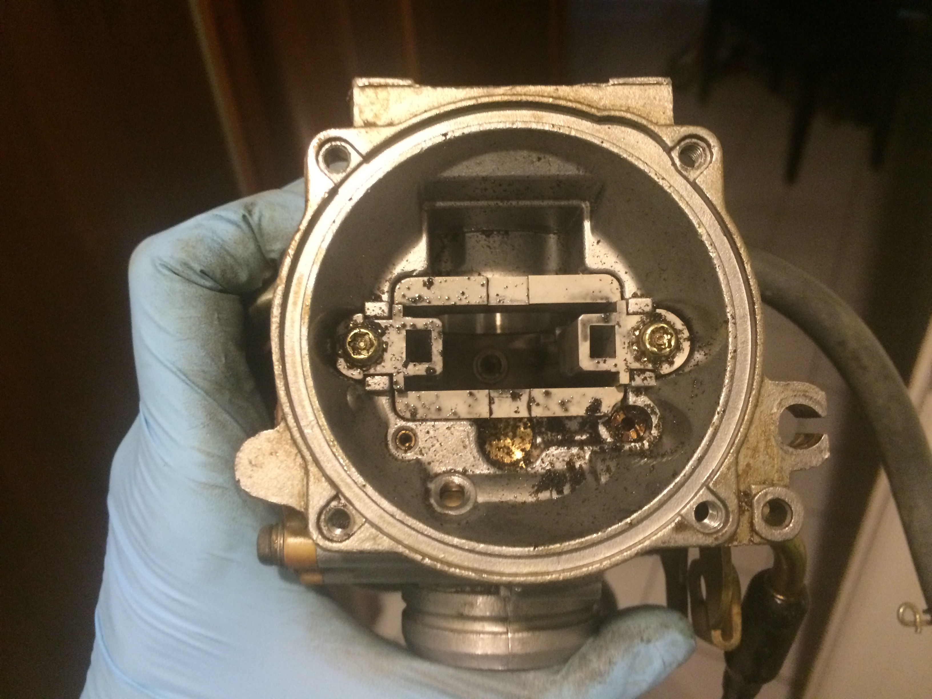
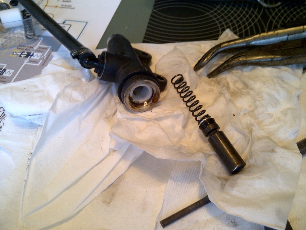
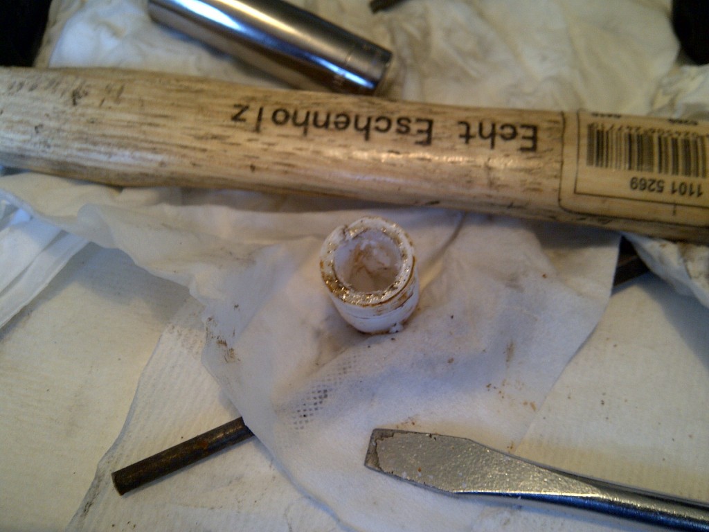
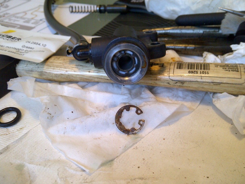
3. Carefully examine the MC. Remove the rubber boot by tugging at it gently. To help it, insert a flat screwdriver into the groove at the base of the MC and gently prise the boot away. Looking down the bore of the MC, you will see the piston at the center, a white spacer surrounding the piston, and a circlip holding it all together. The circlip may be rusty, if it is, you have some work on your hands. See below for a good (bad) example of a rusty circlip.

IMG-20130113-00184

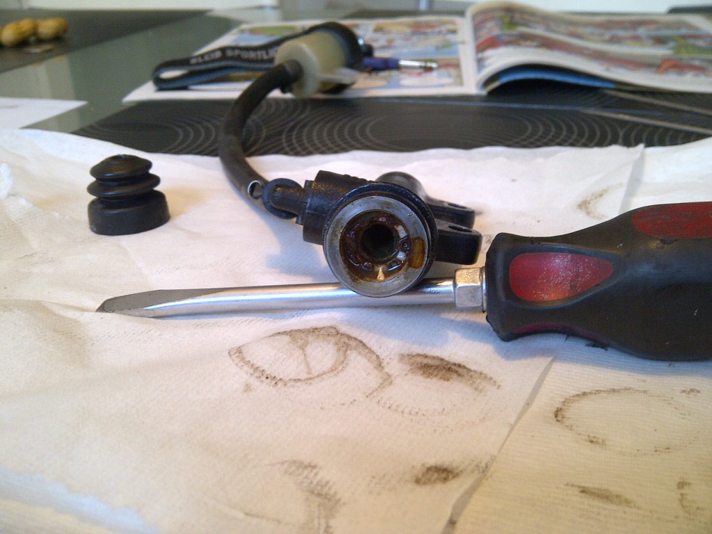
4. Remove the circlip using inside ring removing pliers. If the piston is stuck, use a long 2mm drift or a 2mm Allen wrench to drive it out from the top side. Tap the drift or the Allen key gently with a tack hammer, checking the other end for progress occasionally. When approximately 4mm of piston are exposed, gently grab the piston with long nose pliers and slide it out. This will all require some effort. The spring and spring seat will also come out at this time, or can be shaken out gently. Examine the piston for corrosion and clean it.

IMG-20130113-00185

IMG-20130113-00187

5. Now for the fun. The white sleeve may not slide out willingly. If it did, you would not likely be attempting this repair. A rather easy way to remove the sleeve is to grind or cut a groove in it. I used a 2mm ball-shaped cutting bit on my Dremel and ground out two channels, one the full length of the sleeve. Using the circlip pliers, twist the sleeve in the MC body and slowly work it out. Another way to remove the sleeve is to turn the bits of a 90° circlip tool to the outside and use it as a puller. In either case, take care not to damage the surface of the bore. It is not a sealing surface, but smooth is very important to the cylinder staying functional for any length of time. After removing the white sleeve, remove the o-ring that is still in the bore.

IMG-20130113-00190

6. Once the white sleeve is removed, you will have to clean the inside of the outer bore where the sleeve was sitting. If the circlip was rusty, you will likely also find rust inside of the bore. Using Scotchbrite, steel wool, or very fine sandpaper, remove the red rust from the bore. Clean the bore to remove the residue from this round of cleaning.

IMG-20130113-00188

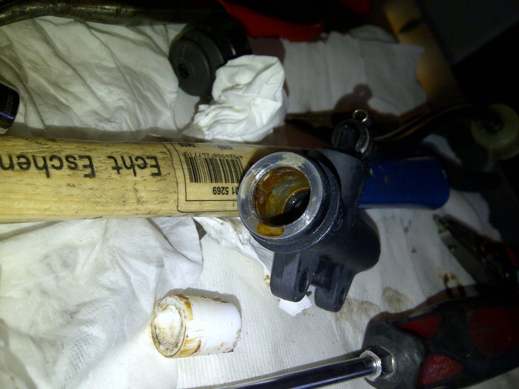
7. This step is critical to determining whether the MC is going to be repairable for any length of time. After the red rust is removed, use a pick to investigate the condition of the outer bore. If you have tiny fingers, they will work, too. Now, you are looking for corrosion of the aluminium cylinder body. This is the corrosion that is causing the piston to stick, not the red rust. Using a pick, gently flake away any aluminium oxide that has built up in the bore. Under the oxide will be pits. There is no getting around this. Fortunately, these pits do not interfere with the operation of the cylinder if they are properly treated prior to reassembly. This process is slow and time-consuming, but will pay off in the end. When you have removed the fluffy stuff, carefully clean the entire MC and the reservoir and feed line. Blow them out well with clean water and air, and dry thoroughly.

8. When you have removed the aluminium oxide from the bore, it is time to open up the rebuild kit and start putting things back together. Remove the white sleeve from the kit and test fit it to the bore. It should float smoothly in the bore with only very slight resistance to turning or sliding. This indicates that the bore is free of oxide. Remove the white sleeve, and coat the inside of the bore with Loctite Silver or Heavy Duty (black) antiseize. Do not use copper-based antiseize! This coating should be very very light. Coat the new o-ring with brake assembly grease (HMW polyoxyethylene, supplied in the kit) and insert it into the bore. Insert the white sleeve and twist it gently in the bore. Assemble the spring to its spring seat, and slide the spring into the bore. Coat the piston and seal with brake assembly grease and insert them into the bore. The piston will stick out a bit.

IMG-20130113-00183

9. To finish the assembly, fit the new circlip to the inside circlip pliers.  Secure the master cylinder body and hold the circlip over the piston. Using a suitable drift, inserted through the center of the circlip, depress the piston into the MC, and secure the circlip. Treat the circlip with a drop of wicking grade low-strength threadlocker and, using a pick, draw the threadlocker around the circlip to coat it evenly.

IMG-20130113-00191

10. Bench bleed the MC and install it to the motorbike, in reverse order of removal. Fully bleed the braking system, including at least one ABS activation in the middle of the process.

Conclusion: The boot on the MC is poorly designed and encourages water to enter the space within the boot. Basically, the boot should be inserted into the MC, not sitting on the outside. This moisture leads to corrosion of the circlip. However, corrosion of the circlip is not the reason the whole thing fails, it is just part of a chain reaction of fail. Once the iron starts to go, it triggers a galvanic reaction in the aluminium and the aluminium begins to corrode. The problem is that aluminium oxide is fluffy. Very fluffy. And very incompressibly crystalline. This increase in volume puts pressure on the white sleeve and eventually causes the piston to bind.

My fix: Forget grease. It won’t hold up. Use a heavy duty anti-seize product like Loctite Silver or Heavy Duty (black) to fill the void between the sleeve and bore, and then coat the circlip with low-strength (green) wicking threadlocker, which is commonly used as an anti-corrosive coating on automotive fasteners. If you are in Aviation and have access to Alodine 1424 or the like, a coating of this on the inside of the sleeve bore (along with overnight drying) will also go a long way to preventing repeat performances.

I rode out to Kalkar Mill on Saturday afternoon to check out the stones. Kalkarermühle is an operating windmill in Kalkar, NRW, Germany, and home to a diverse bunch of people who have decided to keep the windmilling trade alive as volunteer millers. One of the millers is a friend and fellow rider, and introduced me to this neat old technology last fall.

The key to the mill is the stone set. The lower stone, shown here, is fixed and does not move. The upper stone is supported on a pintle that is driven by the familiar sails that catch the wind and power the operation. The entire rig runs at around 120rpm, which is quite speedy, considering that the stones are about 1.6m in diameter. That comes to an edge speed of 24m/s! When the season for milling is low (winter), the millers open the stones for cleaning, resurfacing, and rhynd repairs. On this stone, the darker areas are the wear surfaces, and the grooves are the feeders that feed the grain in.

Fixed stone from Kalkarermühle

Continue Reading

Much more important than people realize, your tyres are riding on this wire…

From my presentation to the Wire Association International in 2004. Still the most wonderful, talented group of engineers I know.

Lubrication in steel wire drawing operations generally brings soap powders to mind. For larger wires this is uniformly the case. The soap powder melts in the wire/die interface and provides a viscous film that supports the drawing force. The fillers and additives in the drawing soap impart polishing, extreme pressure, and many other properties to the lubricants. As wire sizes get smaller, the soap powders become unsuitable for high performance drawing. The viscosity of the molten film is too high, and the film occludes the hole, reducing the wire diameter and eventually breaking the wire. Additives may corrode the wires causing breaks. The polishing aids and other particulate materials may be drawn into the wire, weakening it and resulting in failures. Wet drawing lubricants are required to overcome this problem.

Wet drawing lubricants are based on water and/or oil and have considerably lower viscosities than the molten soaps they replace. This reduces the film thickness and the chances that the film will occlude or block the die orifice. Wet lubricants do not contain particulate materials, so foreign inclusions are not drawn into the surface from the lubricant. The additive level is much lower in a wet lubricant and can be controlled by dilution. The wet lubricants also provide cooling to the operation, a feature absent from dry drawing operations. The wet lubricant requires different maintenance techniques than those required for dry soaps. A comparison of the two types of wet lubricants and their individual requirements for usage will be presented.

Abstract from my 2004 presentation to the Society of Tribologists and Lubrication Engineers….. Probably one of the best papers I have ever given, and winner of the Deutsch award for practical tribology research. That was a big day for me!

Predictive testing of Steel Rolling oils using the Elastohydrodynamic Lubrication Rig

The rolling of steel sheet from continuously cast slabs and coils or ingots to sheet and tin products is a fundamental step in the manufacture of goods worldwide. Slab and sheet reduction is accomplished by plastic deformation of the slab using large metal rolls to apply a force normal to the slab. The contact area between the roll and the slab/sheet must be lubricated to provide proper sheet finish and good tool life. Rolling operations are very large, and it is difficult to test the performance of rolling oils on the mill due to the volume of lubricant and the set-up times required. Development of reliable predictive testing methods is critical for the design of good rolling lubricants.

Rolling oils are typically formulated from fat and mineral oil basestocks with appropriate additive packages and provide hydrodynamic and boundary lubrication to the roll contact. The rolling contact is formed by the plastically deformed sheet and the roll and has three specific zones – the backward slip zone, the neutral point, and the forward slip zone. In both of the slip zones, fresh metal surface is exposed and the process operates in a slip condition. At the neutral point, the contact operates in a true rolling condition. This suggests that a test method with variable slip is for testing and evaluation of rolling lubricant performance.

I’m Katherine, and I’m a chemical tribologist in the metalworking industry. What’s that? A chemical tribologist is a chemist who studies friction and wear. I became interested in this field when I was a co-op student at Drexel University. I co-oped for Apex Alkali Products (now RichardsApex Company), where I learned the fundamentals of lubrication as it applies to wire drawing processes. The work was so interesting that I stayed with Apex for long after my co-op cycle was over! I began to work on lubricant development projects and use bench testing machinery. It was very exciting to see the chemistry I had learned in school in action.

The funny thing is, this all started long before college, or even high school. As a little girl, I had the opportunity to visit the new foundry of the New York Air Brake company (now Knorr Brake). My father is a mechanical engineer (everything in life is a force balance!), and was part of the product design team at the Air Brake. The children on the tour got to do some of the things that the foundry workers did every day. I got to make a sand cast of a complex pnuematic valve assembly. This involved pouring the sand and pressurising the mould. I then inserted little styrofoam blocks into the sand cast to support it under the weight of the molten metal. I put the sand cast onto a conveyor, and followed it to a platform where I was directed to pull a large handle- it was as long as I was tall! The parts came out of the other end of a large machine, and we follwed them around the factory as they were machined and fitted out. Many years later, I realised that I had pulled the ladle and made an iron casting. It was a long time before I figured out what each step of the process was for and what I had actually done, but from the day of the visit on, I was completely fascinated by manufacturing and big metal. The foundry experience shaped my life in ways I wouldn’t appreciate for over 15 years.

After 2 and a half years at Apex, I decided to finish my coursework full time. I left Apex for a year of intense study and graduated from Drexel University in 1994 with my BS in Chemistry.

After graduation, I joined Houghton International, a leading independent manufacturer of metalworking fluids. This is where the fun really got going! I started in the Fluid Power group, learning about hydraulic systems and their lubrication requirements. That didn’t last long, as an opening turned up in the Metal Forming group. Metal forming is the chipless deformation of metals- and wire drawing is one of the many processes that fall under its umbrella. I was right at home!

While working at Houghon, I had many opportunities- I completed my MS in Organometallic Chemistry at Drexel in 1998, and passed my candidacy exams for PhD in January of 2000. I hope to complete my PhD one day. I have also published several research and technology papers (see list below). I have become very involved in the development of new lubricant testing methods which provide more representative pictures of the lubrication system at work in a given process.

I worked with several processes at Houghton- non-ferrous (aluminum and copper) wire drawing, steel wire drawing, hot and cold forging, cold heading, deep drawing, stamping, fine blanking, rolling, extrusion and many other low metal loss processes. I occasionally worked with sintered metals and die casting. I was asked to design lubricants for each of these processes. This required a complete understanding of the process and its lubrication requirements. My mechanics background came in very handy with this part of the job! I then mapped the process by determining the simplest configuration of testing pieces which will give an accurate representation of the conditions of the metal/die contact I was studying. I also developed test methods for the bench tester I planned to use. Some of the testers I used are the Falex pin and vee block rig, the 4-ball EP and 4-ball wear, the ball on three disc, and the Reichert device.

My favourite project is the development of specialised lubricants for the wet drawing of steel filaments. I hope to obtain a patent on this work.

After 7 great years at Houghton, I was approached by Arizona Chemical Company, the chemicals division of International Paper to take over their metalworking program. Arizona takes waste streams from the kraft paper pulping process called black liquor and refines these wastes into pure fatty acids and fatty acid blends. Nearly 30% of the material is made of rosins and rosin acids These important materials play a big role in metalworking by forming strong films which support heavy loads.

I was doing research to study how Arizona’s products can be used in metalworking. It was a lot of fun, and was the opportunity I was looking for to do molecular level development work. Arizona is in Savannah, GA, a beautiful southern city with a lot to offer!

Now I’m at Henkel Corporation outside of Detroit. Back at home, if you ask me!

To learn more about tribology, check out the Society of Tribologists and Lubrication Engineers and the American Society of Mechnical Engineers.